In my first post on this blog, I talked about hardware and using LLMs to generate domain-specific languages for hardware. In the case of a signal generator, regular programming languages like Python are actually an excellent choice.
To realize an LLM signal generator proof of concept, I used Adafruit’s ItsyBitsy Feather M4 board. This has two 12 bit 1 Msps digital-to-analog converters (DACs) that we will use as signal outputs. Further it has a bank of five 1 mega-sample per second (Msps) 12-bit analog-to-digital converters (ADCs), which we will use to set the parameters of our signal.
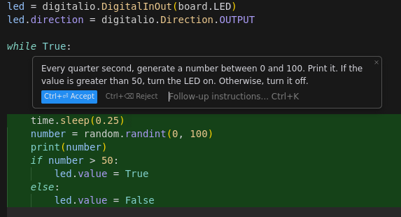
What convinced me that this was possible was running CircutPython on the Feather M4. A board running CircutPython shows up as a mass storage device when we plug it into a PC, with a code.py file on it. When this file is saved the board is restarted and a Python interpreter executes code.py. Opening up this file with Cursor means we can take advantage of LLM code generation directly onto embedded devices!

What’s exciting about this is just how fast the prototyping loop is. Type it out, watch it execute on Ctrl-S.
The next step was to create the harness code for our signal generator, everything around the signal generator function itself.
First we’ll do the imports and declare global variables.
import board
import time
from analogio import AnalogIn, AnalogOut
import math
import random

SIMULATION_TIMESTEP_NS = 1000000  # 1ms
SIMULATION_TIMESTEP_S = SIMULATION_TIMESTEP_NS / 1.0e9

v_in0 = AnalogIn(board.A2)
v_in1 = AnalogIn(board.A3)
v_in2 = AnalogIn(board.A4)
v_in3 = AnalogIn(board.A5)

v_out0 = AnalogOut(board.A0)
v_out1 = AnalogOut(board.A1)

gen = None  # To be set by LLM.
For my signal generator I want both the input potentiometers to represent parameters that have some unit and range, and also the output pins.
class RangedInputPin(object):
    def __init__(self, pin, min_value: float, max_value: float):
        self.pin = pin
        self.min_value = min_value
        self.max_value = max_value

    def read_to_range(self):
        voltage = self.pin.value / 65535
        return self.min_value + (voltage * (self.max_value - self.min_value))

class RangedOutputPin(object):
    def __init__(self, pin, min_value: float, max_value: float):
        self.pin = pin
        self.min_value = min_value
        self.max_value = max_value

    def write_from_range(self, value):
        value = max(self.min_value, min(value, self.max_value))

        scale = (value - self.min_value) / (self.max_value - self.min_value)
        mapped_value = round(scale * 65535)
        mapped_value = int(max(0, min(mapped_value, 65535)))
        self.pin.value = mapped_value
After this spot is where we’ll ask the LLM to populate code, including setting the gen variable to a class with a timestep method. Then comes the main loop:
while True:
    start_time = time.monotonic_ns()

    x, y = gen.timestep(SIMULATION_TIMESTEP_S, input0.read_to_range(), input1.read_to_range(), input2.read_to_range(), input3.read_to_range())
    output0.write_from_range(x)
    output1.write_from_range(y)

    end_time = time.monotonic_ns()
    delta_time = end_time - start_time
    wait_remaining = SIMULATION_TIMESTEP_NS - delta_time
    if wait_remaining > 0:
        time.sleep(wait_remaining / 1e9)
Ideally we want our simulation to step ahead at a regular interval.
You may notice that our timestep interval is extremely long at 1 ms: that means we can’t simulate a signal at a speed greater than 1 kHz! Unfortunately CircuitPython is extremely slow: for a very simple signal model that I’ll describe later the loop took 0.7 ms. To move away from a proof of concept and into a prototype I’ll have to drop CircuitPython in favor of Rust.
With the harness in place it’s time to ask an LLM to generate code. I want the LLM to do so in a two-step process. First I’ll have it generate a mathematical model that utilizes the inputs, then I’ll have it translate that to code. Here’s the first prompt:
You are to translate the user’s natural language input into signal generation code.
The user will have access to four knobs which represent the variables that change the behavior of the signal. The hardware has two outputs.
First we will describe a mathematical model that satisfies the users input.
The user has provided the following instructions for a signal to generate: {{ prompt }}
Describe a mathematical model for this process.
For a prompt of “Generate a sine wave” ChatGPT gave me:
Certainly! A sine wave can be mathematically described by the following equation:
\[y(t) = A \times \sin(2\pi f t + \phi)\]
Where:
- \(y(t)\) represents the output value of the signal at a given time \(t\).
- \(A\) represents the amplitude of the sine wave.
- \(f\) represents the frequency of the sine wave (how many oscillations it completes in a unit of time).
- \(\phi\) represents the phase shift of the sine wave.
- \(t\) is the time variable.
Given that the user has access to four knobs, we can let each knob control a different parameter of the sine wave:
- Knob 1: Controls the amplitude \(A\) (e.g., range from 0 to 5).
- Knob 2: Controls the frequency \(f\) (e.g., range from 1Hz to 100Hz).
- Knob 3: Controls the phase shift \(\phi\) (e.g., range from 0 to \(2\pi\)).
- Knob 4: It can control another parameter, like the offset (bias) from the baseline. Let’s call this parameter \(B\). This makes the equation: \(y(t) = A \times \sin(2\pi f t + \phi) + B\). This allows the user to shift the sine wave up or down along the y-axis.
Given that there are two hardware outputs, you can generate two separate sine waves with separate sets of parameters, or perhaps one output provides the sine wave, and the other output provides another waveform (like a cosine wave) or some transformation of the sine wave.
To simplify, for a single output producing the sine wave, the signal generation code based on the knobs could look something like:
Where A, f, phi, and B are the values from the four knobs respectively. The t parameter represents time and would be continuously updated to generate the signal in real-time.
Now we’ll pass in the harness code and provide an example for the LLM to generate from.
We will now create CircuitPython code to physically generate those outputs based on physical inputs. The header for this file:
-- snip, see above --You are two generate the output in two parts.
The first part maps the input and output variables from our model to inputs and outputs. Assign reasonable values for max and min.
Example for squaring x: 1. Variable Assignment
input0 = RangedInputPin(v_in0, 0, 10)
output0 = RangedOutputPin(v_out0, 0, 1000)
The second part creates the generation class and function. The class should carry any variables the signal generation might need. The class MUST have a function that satisfies the interface
If any of the inputs are unused, ignore them. If an output is unused, set it to 0.0.
Example for squaring x: 2. Generation Class and Function
class SignalGenFn:
    def __init__(self):
        pass

    def timestep(self, delta_t: float, input1: float, input2: float, input3: float, input4: float) -> (float, float):
        return (input1 * input1, 0.0)
Follow the examples when responding.
Part 1: Variable Assignment
In this example, the input variables represent the four knobs, and the output variables represent the two outputs. Assign reasonable min and max values to these variables.
amplitude_input = RangedInputPin(v_in0, 0.0, 5.0)  # A: Amplitude (0 to 5)
frequency_input = RangedInputPin(v_in1, 1.0, 1000.0)  # f: Frequency (1Hz to 1kHz)
phase_input = RangedInputPin(v_in2, 0.0, 2 * math.pi)  # φ: Phase (0 to 2π)
offset_input = RangedInputPin(v_in3, -5.0, 5.0)  # B: Offset (-5 to 5)

output0 = RangedOutputPin(v_out0, -10.0, 10.0)  # Output0 range (-10 to 10)
output1 = RangedOutputPin(v_out1, -10.0, 10.0)  # Output1 range (-10 to 10)
Part 2: Generation Class and Function
Define a class for the signal generator, implementing a timestep function which calculates the sine wave based on the provided inputs.
class SineWaveSignalGen:
    def __init__(self):
        # Initialize time variable
        self.t = 0.0

    def timestep(self, delta_t: float, amplitude: float, frequency: float, phase: float, offset: float) -> (float, float):
        # Calculate the sine wave value
        sine_value = amplitude * math.sin(2 * math.pi * frequency * self.t + phase) + offset

        # Update time variable
        self.t += delta_t

        # Return the calculated sine value on output0 and 0.0 on output1
        return (sine_value, 0.0)
That looks good to me. Let’s wire up a board:

Not my best wire routing job, but oh well. Let’s fire it up:
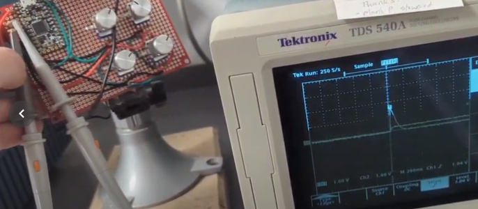
It works! Kind of! We’re getting a very noisy signal, which I suspect is EMI. I didn’t put any filter caps on the board. The wave quickly devolves once we get into higher frequencies due to the slow timing issues.
So far we’ve just created a much worse benchtop signal generator. Let’s try something more interesting. Let’s ask instead for “Generate signals representing the way a predator and a prey population changes over time.”
ChatGPT performs very well here:
Certainly! One of the most commonly used mathematical models to represent the interaction between a predator and a prey population over time is the Lotka-Volterra system of differential equations.
The model describes the dynamics of the predator-prey interactions in the following way:
- The prey population is assumed to have an unlimited food supply and will grow exponentially in the absence of predators.
- The predator population will starve and decrease in the absence of prey.
- The rate at which predators consume prey is proportional to the product of the predator and prey populations.
Given:
- \(x(t)\) = number of prey at time \(t\)
- \(y(t)\) = number of predators at time \(t\)
The equations are:
\[\frac{dx}{dt} = \alpha x - \beta x y\] \[\frac{dy}{dt} = -\gamma y + \delta x y\]
Where:
- \(\alpha\) is the natural growth rate of the prey in the absence of predators.
- \(\beta\) is the rate at which the predators consume the prey.
- \(\gamma\) is the natural death rate of the predators in the absence of prey.
- \(\delta\) is the rate at which predators increase by consuming prey.
Now, the user has access to four knobs. We can use these knobs to control the four parameters \(\alpha, \beta, \gamma, \delta\). As the user turns the knobs, the values of these parameters change, and consequently, the behavior of the predator and prey populations changes in response.
Thus:
- Knob 1: Controls \(\alpha\) (Natural growth rate of the prey)
- Knob 2: Controls \(\beta\) (Rate of prey consumption by predators)
- Knob 3: Controls \(\gamma\) (Natural death rate of predators)
- Knob 4: Controls \(\delta\) (Rate of predator growth from consuming prey)
The two outputs would be:
- Output 1: \(x(t)\) (Prey population over time)
- Output 2: \(y(t)\) (Predator population over time)
In a real-world implementation, numerical methods (e.g., the Euler method or the Runge-Kutta method) would be used to solve these differential equations iteratively to generate the signals over time.
Asking for code we get:
# Knob 1: Controls α (Natural growth rate of the prey)
input0 = RangedInputPin(v_in0, 0, 2)  # α ranges typically between 0 and 2

# Knob 2: Controls β (Rate of prey consumption by predators)
input1 = RangedInputPin(v_in1, 0, 1)  # β ranges typically between 0 and 1

# Knob 3: Controls γ (Natural death rate of predators)
input2 = RangedInputPin(v_in2, 0, 2)  # γ ranges typically between 0 and 2

# Knob 4: Controls δ (Rate of predator growth from consuming prey)
input3 = RangedInputPin(v_in3, 0, 1)  # δ ranges typically between 0 and 1

# Output 1: Prey population over time (x(t))
output0 = RangedOutputPin(v_out0, 0, 1000)  # Assuming prey population ranges between 0 and 1000

# Output 2: Predator population over time (y(t))
output1 = RangedOutputPin(v_out1, 0, 500)   # Assuming predator population ranges between 0 and 500

class LotkaVolterraGen:
    def __init__(self):
        # Initial populations
        self.x = 500  # Initial prey population
        self.y = 250  # Initial predator population

    def timestep(self, delta_t: float, alpha: float, beta: float, gamma: float, delta: float) -> (float, float):
        # Using the Lotka-Volterra equations:
        dx = (alpha * self.x - beta * self.x * self.y) * delta_t
        dy = (-gamma * self.y + delta * self.x * self.y) * delta_t

        # Update the populations:
        self.x += dx
        self.y += dy

        # Ensure populations don't go below zero:
        self.x = max(0, self.x)
        self.y = max(0, self.y)

        # Return the updated populations:
        return (self.x, self.y)
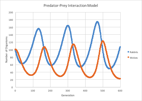
What I wanted to see was some nice periodic waveforms like this:

But I was struggling to get any interesting signals out of it while fiddling the knobs.

Periodic and chaotic behavior often depends on a very particular set of initial conditions, so it’s possible the knobs are a bad choice here. They’re noisy enough that you get constant least significant bit flips.
The good news is that this is clearly a feasible approach. I want to at least be able to generate signals at audio speeds (200 Hz to 20 kHz), which I should be able to get with a Rust-based system (and proper timer interrupts instead of time.sleep()). Making my own PCB should take care of the EMI issues.
Then the question becomes: how should this thing be used? One possible avenue is as an educational tool for understanding the behavior of different signals, and also the behavior of a circuit under the stimulation of this generator. For instance, imagine mapping the predator population to a voltage-controlled oscillator, such that it rings at a high frequency when the population is high, and creates a bass tone at 0. By adding these extra sensory outputs to a model we can more intuitively understand their behavior. Charles Rosenbauer has written about this, predicting:
Sensory augmentation tools will be developed for software development. It will be possible to listen to sounds that communicate useful information about the structure and behavior of code.Or perhaps it might support something like Show me what the response of this filter circuit around it's 3 db point – there are many possibilities!
